

How to Choose a Rubber Deflashing Machine
Choosing a Rubber Deflashing Machine starts with the parts you actually produce, not the most impressive machine specification. Rubber compound, part size, flash thickness, and component geometry all affect how reliably excess material can be removed. A small molded seal with thin flash may need a different process from a thick, complex automotive component. Details matter.
Compare mechanical trimming and cryogenic deflashing against your part requirements. Mechanical systems can suit accessible flash, while cryogenic processes may help with intricate shapes and hard-to-reach edges. Neither option is automatically best. Ask suppliers to process representative samples, then inspect the results for surface damage, leftover flash, and consistency across a batch. One successful sample is useful, but repeatability matters more.
Consider practical operating needs, too: expected throughput, loading method, floor space, noise, maintenance access, and operator training. Review how the machine handles different part sizes and compound variations. A low purchase price can be misleading if setup is difficult or routine cleaning takes longer than expected. Check service support and spare-parts availability before committing. Small omissions add up.
Real production is rarely as neat as a brochure suggests. Your parts may vary. That is worth planning for. Keep room for a trial run, and record the settings that produce acceptable results. The right Rubber Deflashing Machine should match your components, workflow, and quality expectations, while leaving enough flexibility for changes you have not encountered yet.
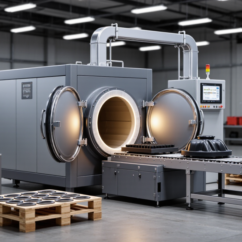
Identify the Rubber Parts and Flash Removal Requirements
Before choosing a rubber deflashing machine, identify the part’s material, shape, and flash location. EPDM seals, silicone gaskets, and nitrile O-rings behave differently under impact and abrasion. Record hardness, wall thickness, delicate edges, and any holes or grooves that must stay open. A thin fin along a mould seam is not the same problem as a thick gate remnant. Small details matter.
Define the acceptable result with a drawing or sample, not just “clean.” Note the maximum flash thickness, critical dimensions, surface-finish limits, and whether parts can tolerate tumbling or contact with media. The International Rubber Study Group’s World Rubber Industry Outlook 2024 estimated global rubber demand at about 31.4 million tonnes for 2024. That broad figure signals a large, varied industry; it does not tell you how a specific seal will respond to deflashing. Test real parts.
Ask the supplier to process representative parts from different cavities and production runs. Inspect edges under magnification, then check dimensions and functional fit. For thin diaphragms, even slight edge damage may matter. For robust moulded components, a higher-throughput process may be acceptable. I would not rely on one perfect sample; production variation can change the result. Keep samples, settings, and inspection records together.
Compare Deflashing Methods and Machine Technologies
How to Choose a Rubber Deflashing Machine
Compare methods against the part, not just the quoted cycle time. Manual trimming can suit prototypes and low volumes, but results depend heavily on operator skill. Tumbling removes flash through repeated contact with media; check that delicate features can tolerate the impact. Cryogenic deflashing cools parts until thin flash becomes brittle, then uses media to remove it. It can process many parts per batch, but settings must match the rubber compound and part geometry. Mechanical cutting offers direct edge control, though tooling and fixturing may add setup time.
Machine technology matters, too. Compare batch and continuous systems, temperature controls, media handling, and how easily settings can be repeated. The U.S. Department of Energy’s Improving Compressed Air System Performance guide reports that compressed air accounts for about 10% of electricity use in U.S. manufacturing, with higher shares in some plants. For air-driven equipment, include air demand in the operating-cost comparison; it is easy to overlook.
Tips: Run a trial with actual molded parts. Inspect edges under magnification, count damaged parts, and record cycle time and energy use. A clean edge is not enough if the process varies between batches.
How to Choose a Rubber Deflashing Machine
Compare typical process temperatures for common deflashing methods.
Cryogenic deflashing uses a cooled chamber to embrittle flash before it is removed by tumbling media. Mechanical tumbling and manual trimming are generally performed near room temperature. Values are approximate process-environment ranges, not machine specifications; actual conditions vary with the rubber compound, part geometry, and equipment. Consider part quality, throughput, labor, and material compatibility when choosing a method.
Match Machine Capacity to Production Volume and Part Size
Choosing a rubber deflashing machine starts with the work you actually run, not the largest number on a brochure. Estimate daily output, then compare it with usable batch capacity and cycle time. A machine rated for 20 kilograms per hour may still fall short if loading, cooling, and inspection add long pauses. Count those minutes. Keep some reserve for busy shifts, but avoid capacity that sits idle most of the week.
Part size matters just as much as throughput. Measure the largest component, including protrusions, and check the chamber’s usable dimensions. A part that fits on paper may still block circulation or collide with other parts during a batch. Leave room for movement. Small parts can also be inefficient when packed too tightly, since crowded loads may leave flash unevenly removed. Mixed sizes deserve a test run; one setting may not suit every geometry.
In practice, estimates can be wrong. Run representative parts at the intended batch size and inspect the results before committing to a production rate. Note cycle time, loading effort, and any damage or missed flash. A slower, consistent batch may serve better than a faster cycle that needs repeated sorting. Also consider whether the machine can handle occasional oversized parts without disrupting normal production.
Assess Material Compatibility, Safety, and Operating Costs
Choosing a rubber deflashing machine starts with the compound, not the catalog.
Natural rubber, silicone, and EPDM can respond differently to cold, impact, and abrasion. Check hardness, flash thickness, part shape, and thin edges that could chip. Ask for representative parts to be processed, then inspect dimensions and surface finish closely. A clean-looking part may still have stressed edges. Record results across several batches, not just one successful run. This takes time. A sample test can mislead if production parts vary more than expected.
Before purchase, review guards, emergency stops, loading access, and maintenance isolation points. For cryogenic systems, confirm ventilation and oxygen monitoring where the equipment design or site assessment requires them. Operators need clear procedures for cold-contact risks; gloves alone are not a complete plan. Check noise, dust, and waste handling too. Estimate cost per acceptable part, not just purchase price. Include electricity, nitrogen or media, labor, tooling, cleaning, and scheduled maintenance. A faster cycle may increase scrap or tooling costs. Request realistic throughput data and verify it with your own parts. I would also allow for downtime; maintenance rarely follows a perfect schedule.
Verify Performance Through Trials and Supplier Support
A supplier’s demonstration should use your own rubber compound, cure state, and part geometry. A glossy sample from another material proves little. Bring parts with thin flash, deep grooves, and the tightest corners on your drawing. Run a timed trial, then inspect at least 100 pieces for leftover flash, surface damage, and dimensional change. Record cycle time and reject count. Run it twice. The second run can reveal inconsistent feeding or tool wear. Use ISO 3302-1:2014 to confirm the applicable dimensional-tolerance class for molded rubber parts; visual cleanliness alone is not a pass.
Supplier support matters after the demonstration. Ask who will set the machine, train operators, and troubleshoot changes in compound or part shape. Request a written acceptance sheet with agreed sample sizes, defect limits, and response times. The ISO Survey 2022 reported 1,265,216 valid ISO 9001 certificates worldwide. That figure shows how common certified quality systems are; it does not prove that a specific machine will meet your process needs. Ask for service records, spare-part lead times, and a clear escalation contact. I would also keep one weakness visible: a short trial may miss seasonal variation in rubber hardness. Plan a follow-up run under normal production conditions, and preserve the results for comparison.
| How to Choose a Rubber Deflashing Machine - Verify Performance Through Trials and Supplier Support | ||||
|---|---|---|---|---|
| Practical trial matrix: Use representative production parts and agree on acceptance limits before testing. The example quantities below are trial-planning suggestions, not universal specifications. | ||||
| Evaluation dimension | What to record | Trial method | Acceptance evidence | Why it matters |
| Part and material match | Rubber compound, part number, nominal dimensions, hardness scale and value, and flash location or thickness. | Submit production parts from the actual compound and tooling. Include parts with typical variation, not only hand-picked samples. | A written trial record identifies the tested part, material, incoming condition, and any parts excluded from the test. | Deflashing results can change with compound, geometry, flash condition, and part temperature. |
| Flash removal | Residual flash by location, number of parts meeting the agreed visual or dimensional standard, and any rework required. | Inspect parts under consistent lighting and magnification where appropriate. Use a defined sample size, such as 30 parts per run, and record defects by type. | Results meet the agreed drawing, visual standard, or customer inspection criteria; borderline parts are identified separately. | “Clean” should have a defined inspection standard rather than rely on a general visual claim. |
| Part damage and dimensional condition | Cuts, nicks, surface marks, deformation, dimensional changes, or damage to functional edges. | Compare processed parts with unprocessed controls. Measure critical features using the same method before and after processing. | No damage exceeds the agreed defect limits, and critical dimensions remain within the part drawing tolerances. | A process that removes flash but harms the sealing surface or critical geometry is not suitable. |
| Throughput and cycle time | Parts loaded, accepted parts, processing time, unloading time, and operator handling time. | Time complete runs under the proposed production loading pattern. Repeat the run to account for loading and unloading variation. | Recorded output meets the required production rate after accounting for inspection, rework, and routine handling. | Machine cycle time alone may not represent actual production throughput. |
| Repeatability | Pass rate, residual-flash observations, damage findings, and cycle time for each run. | Run the same agreed recipe at least three times using comparable parts and loading conditions. | All runs meet the agreed acceptance criteria, with run-to-run variation documented and explained. | Repeated trials help reveal inconsistent results that a single demonstration may miss. |
| Process settings and operating cost | Machine settings, media or consumable use where applicable, energy use where measurable, cleaning needs, and changeover time. | Ask the supplier to document the settings used and the consumables required for the tested part and batch size. | The process recipe is reproducible, and expected operating inputs can be reviewed against the buyer’s production plan. | Settings and consumables affect both ongoing cost and the ability to reproduce trial results. |
| Changeover and operator requirements | Setup steps, tooling or recipe changes, training time, operator tasks, and required personal protective equipment. | Observe a changeover between representative parts or recipes and record the steps that require supplier assistance. | Setup instructions are documented, and the required operator training and safety measures are identified. | Frequent product changes can make setup time and ease of use important selection factors. |
| Supplier support and trial documentation | Trial report, proposed machine configuration, training, installation scope, spare parts, service coverage, and response commitments. | Request written answers to technical questions and a support plan covering installation, commissioning, troubleshooting, and maintenance. | Responsibilities, deliverables, service terms, and agreed response times are documented before purchase. | Clear support commitments make it easier to move from a successful trial to stable production. |
| Decision rule: Select a machine only after the trial meets written quality, throughput, repeatability, safety, and support requirements. Confirm that the tested parts and process conditions match the intended production application. | ||||